GCK
Ⅰ.General
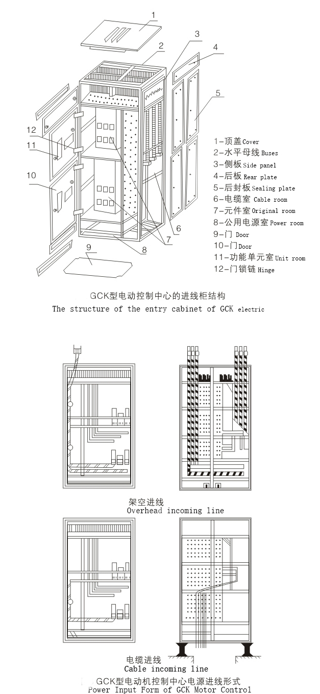
GCK Low-voltage extraction switchgear is mainly composed of some combined motor control units and other functional units. These units are mounted in a closed metal cabinet by overlapping the upper and lower parts. Each cabinet body is connected with a horizontal bus set above the cabinet body, and the functional units of the same cabinet body are connected with a vertical bus in parallel. The cabinet body is divided into four isolation zones: horizontal bus zone, vertical bus zone, cable zone and equipment installation zone. Functional units are installed in their respective small rooms. When any functional unit has an accident, it will not affect other units and prevent the accident from expanding.
This product meets the JB/T9661-1999 standard. This product adopts IP40 protection level stipulated by IEC114. When all doors and guards are closed, or when doors are opened and functional units are moved out, it can reach corresponding protection level, which can ensure personal safety. The product is equipped with perfect and reliable grounding system and protection circuit. All functional units can break short-circuit current according to the specified performance requirements. The input unit has three-stage protection characteristics. Therefore, the reliability of power supply and the safety of equipment and system can be guaranteed. All functional units can be connected with PC wiring board (programmable logic controller) or microprocessor through interface. As the executive unit of automatic control system, other functional units and functional combinations can be provided according to user's needs. This product is suitable for 380V AC circuit with 50Hz frequency.
Ⅱ.Type Meaning
![]()
![]()
![]()
![]()
![]()
![]()
![]()
![]()
![]()
![]()
![]()
![]()
![]()
![]()
![]()
![]()
![]() G C K —
G C K —![]()
![]() 主电路方案 Main circuit scheme
主电路方案 Main circuit scheme
![]() 短时耐受电流(kA)Short-term withstand current (kA)
短时耐受电流(kA)Short-term withstand current (kA)
![]() 额定电流(A)Rated current (A)
额定电流(A)Rated current (A)
![]() 设计序号 Design Serial Number
设计序号 Design Serial Number
![]() 控制中心 Control center
控制中心 Control center
![]() 抽出式 Extraction type
抽出式 Extraction type
![]() 封闭式柜 Closed cabinet
封闭式柜 Closed cabinet
Ⅲ.Structural characteristics
1. Major electrical properties meet IEC standards and NEMA standards of the American Association of Electrical Manufacturers.
2. The main switch has three sections (instantaneous, short delay and overload) protection. In order to cooperate with the next main switch (with instantaneous and overload protection), the instantaneous section is cancelled and the step-over tripping is avoided. It has self-switching, no self-switching and switching devices for selection.
3. Horizontal bus has two types: single bus segment and non-segment. When single bus segment is used, bus switch also has self-switching, no self-switching and switching devices.
4. Motor control circuit has short-circuit instantaneous, overload, under-voltage release and Phase-break protection.
5. The AC contacts in each functional unit are operated silently, which has the function of energy saving. At the same time, when the power supply disappears, it has the characteristics of delayed release (greater than 0.3s, less than 0.5s). Therefore, when the starting relays of each motor are not installed, the power supply can be restored within 0.3 seconds (reclosure or self-switching time of standby power supply is less than 0.3 seconds), so as to ensure the continued operation of the motor.
6. The main switch of feeder circuit has instantaneous and overload protection, and leakage protection can be added when users need it.
7. The receiving circuit is equipped with ammeters, active and reactive watt-hour meters. The feeder circuit of 250A and above can be equipped with or without ammeters and watt-hour meters. Other circuits larger than 37kW or 60A are equipped with ammeters.
8. Lighting and alarm devices may be installed in case of accidents.
Ⅳ.Electrical parameters
No. | Item | Parameter | |
1 | Standard | IEC439 NEMA ICS-2-322 | |
2 | Protection level | IEC IP40,NEMA TYPE-1 | |
4 | Rated voltage (V) | AC660 , 380 | |
5 | Frequency(HZ) | 50 | |
6 | Rated insulation voltage(V) | 660 | |
7 | Control motor capacity (kW) | 0.45~155 | |
8 | Mechanical life (Times) | 500 | |
9 | Rated current (A) | Horizontal bus bar | 1600、3150 |
10 | Vertical bus bar | 630 | |
11 | Main Circuit Contact Plug-in | 160、250、400、630 | |
12 | Auxiliary Circuit Contact Plug-in | 20 | |
13 | Maximum current of feeder circuit | 160、250、400、630 | |
14 | Maximum Current of Electric Circuit | 1000、1600~2000、2500 | |
15 | Rated short-term withstand current (KV) | Effective value | 50、80 |
16 | Peak value | 105、176 | |
17 | Power frequency withstand voltage(V/1min) | 2500 | |
Ⅴ.Conditions of Use
1. The elevation does not exceed 2000m.
2. The ambient air temperature should not be higher than + 40℃, and the average temperature within 24 hours should not be higher than + 35℃. The ambient air temperature is not less than - 5℃.
3. Atmospheric conditions: the air is clean, the relative humidity does not exceed 50% at + 40℃, and higher relative humidity is allowed at lower temperatures, such as 90% at + 20℃. Consideration should be given to the effect of occasional condensation due to temperature changes.
4. Places free from fire, explosive hazards, serious pollution, chemical corrosion and violent vibration.
5. Inclination with the vertical plane shall not exceed 5 degrees.
6. The control center is suitable for transportation and storage of the following temperatures: - 25℃~55℃, within a short period of time (no more than 24 hours) no more than + 70℃.
Ⅵ.Outward Size& Input Way

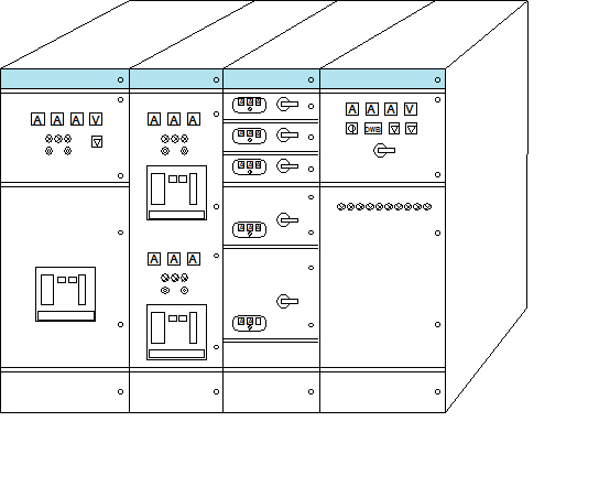
Ⅶ.Combination mode


Ⅷ.Scope of Delivery
The following documents and annexes shall be provided for supply
1. Qualification Certificate
2. Packing list
3.Instructions for Use
4.Exit Inspection Report
5.Electrical diagrams
6.Key and handle
Ⅸ.Instructions for Order
1. Main circuit scheme and combination arrangement;
2. Auxiliary circuit control and wiring principle;
3. The layout of switchgear in distribution room;
4. Input and outgoing forms and interface requirements;
5. Detailed specifications and parameters of components installed in cabinet;
6. The color of paint film on the surface of switchgear, or according to our company's standards.


